


A perforated conveyor belt can fit the machine and still fail to hold a sheet, pouch, or small component steadily. Hole diameter alone does not explain the result: the product footprint, vacuum bed, hole spacing, and exposed openings all matter. On a printing, packaging, or inspection line, an unsuitable layout can turn a replacement belt into a positioning problem. This guide explains how to specify hole size and pattern for a vacuum conveyor, compare candidate layouts, and prepare a drawing that a belt fabricator can review. You will also learn which dimensions can be calculated and which require confirmation on the actual equipment.
How vacuum conveying changes the hole specification
Specify the belt around the product and vacuum bed together. A vacuum conveyor draws air through the belt to help keep items in position. Dorner vacuum conveyor guidance describes a perforated belt working with a vacuum chamber and a customized bed plate. This article concerns lightweight PVC and PU belt fabrication for that arrangement.
Separate open area from effective holding area
Schmalz explanation of vacuum holding force relates suction-cup holding force to pressure difference and effective suction area. That physical relationship is useful background, but a perforated conveyor is not a sealed suction cup. Do not treat either the full product footprint or the sum of hole areas as a verified holding area. The contact surface, channels, leakage, and operating pressure determine what the machine actually achieves.
For specification work, keep three questions separate: Does the belt provide the required air paths? Does the vacuum system sustain the required conditions as products arrive and leave? Does the finished belt support and transport the product without unacceptable movement or marking? A hole drawing answers only part of this review.
Record the product and vacuum bed before choosing holes
Start with the smallest and least stable product that must run on the line. Record the real contact surface, not just the outer dimensions. A pouch may have seams and folds; a component may have a recessed underside; paper and card may vary in air permeability. These details belong in the specification brief rather than being left for the fabricator to guess.
| Input | Record before design | Purpose |
| Product footprint | Minimum length along travel and usable contact width | Check coverage at every pattern position |
| Product condition | Flatness, seams, porosity and marking limits | Identify sealing and support questions |
| Operating motion | Speed, acceleration, stops, orientation and feed spacing | Define the actual handling task |
| Vacuum bed | Slot widths, lane centers, zone lengths and transfer boundaries | Locate where holes can communicate with vacuum |
| Vacuum source | Source model, pressure and flow information, measuring location | Give the equipment designer operating context |
| Finished belt | Width, endless length, construction, splice and guide layout | Connect the hole drawing to the complete belt |
This is a proposed information checklist, not a universal machine specification. Dorner vacuum conveyor guidance confirms that hole geometry and vacuum areas are application-specific. For porous products, Schmalz flow restrictor application notes illustrate why controlling airflow also matters; the component specifications are not conveyor belt dimensions.
Overlay product positions on the bed drawing
Ask the equipment owner for a top view showing vacuum lanes and a section showing the belt support. Mark the intended product centerline, allowed side movement, and entry and release points. Check those positions against the proposed holes. A product centered in a photograph does not prove that the same layout will cover the active holes when feeding varies.
Specify hole diameter and pitch separately
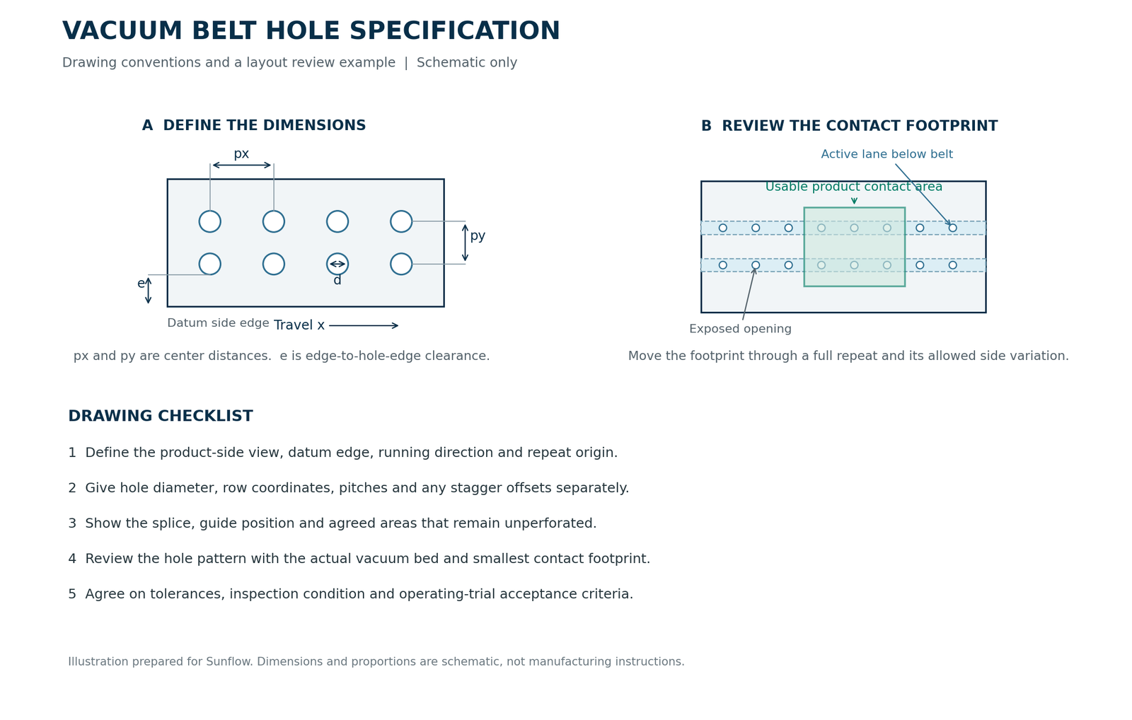
Give the hole diameter and its center position as separate dimensions. Use one coordinate system: x follows belt travel and y runs across the width. State whether the drawing is viewed from the product side or the underside. This prevents an asymmetric layout from being mirrored during fabrication.
| Symbol | Definition | Drawing instruction |
| d | Finished round-hole diameter | State diameter and agreed tolerance |
| px | Longitudinal center-to-center pitch | Measure along belt travel |
| py | Transverse center-to-center pitch | Use for a regular array across the belt |
| yj | Center position of a named hole row | Measure from the stated side datum |
| e | Clear material from belt edge to nearest hole edge | Distinguish it from an edge-to-center dimension |
| g | Clear gap between equal adjacent holes in one straight row | For that row, g equals pitch minus d |
Use diameter as a candidate dimension
There is no single correct diameter for every vacuum conveyor. Forbo customized perforation examples show that perforation shape and pattern can be tailored to the process. The published equipment capabilities belong to Forbo. They do not establish Sunflow’s minimum hole diameter, tolerance, or production method.
For each candidate diameter, ask the fabricator to review hole quality, material remaining between holes, the belt edge, and the splice. Ask the machine owner to check product support and airflow. Will a thin product bridge the opening without an unacceptable mark? Record the agreed inspection or trial method. Do not turn an untested answer into a production drawing.
Calculate geometric open area with a stated denominator
For round holes, geometry gives the area of one opening. The following equations compare drawings; they do not calculate airflow or holding force.
Here Ah is one hole area, d is the finished diameter, N is the number of holes inside the chosen reference area, and Aref is that reference belt area. Keep units consistent. A whole-belt percentage includes solid edges and any unperforated splice region; a local percentage may describe only a perforated band. Label the denominator so the figures can be compared.
Dorner vacuum blower design discussion connects blower selection with total vacuum-hole area and required pressure. Consequently, an open-area percentage is a geometry descriptor, not an approval criterion. Submit the pattern and operating conditions together for review.
Match the pattern to the product footprint and vacuum lanes
A useful pattern must remain compatible as the belt moves. Review a full repeat against the smallest product, its allowable position variation, and the stationary vacuum bed. A hole that is covered by the product but passes over solid bed material does not provide the same connection as a hole over an active channel. Trace the air path rather than judging the pattern by appearance.
Choose the arrangement from the machine layout
| Arrangement | What to specify | Review before approval |
| Straight rows | Row center coordinates and longitudinal repeat | Product coverage and registration with bed lanes |
| Staggered array | Both pitches and the offset between adjacent rows | Coverage at the offset positions and bed compatibility |
| Selected perforated lanes | Each lane or row location and the solid areas between them | Smallest product footprint and exposed active openings |
| Irregular or zoned layout | Coordinates or a dimensioned repeat for every distinct area | Product timing, loop closure and release requirements |
This matrix is an engineering review aid, not a ranking of patterns. Forbo customized perforation examples illustrate application-specific perforations and channels; Dorner vacuum conveyor guidance describes customized vacuum areas. These sources do not establish that a staggered or denser layout is always better. Choose the arrangement that the actual bed and product can use.
Check coverage throughout one complete repeat
Move the minimum product footprint across one longitudinal repeat on the drawing. Check the beginning, intermediate positions, and the repeat boundary. Include the specified sideways movement. Count fully covered holes connected to the vacuum bed, and flag openings that become partially covered or exposed. For irregular products, use the actual contact outline rather than a bounding rectangle.
For an OEM-specific illustration, the Dorner 2200 and 3200 specification sheets specify that the vacuum-hole lead should keep at least two hole patterns under the product. The same document gives different minimum row spacing for its 2200 and 3200 systems. Those requirements belong to those conveyor platforms. Use them to see why product dimensions and bed construction matter, not as universal Sunflow fabrication limits.
Review uncovered openings and the release point
Schmalz guidance on uncovered suction cells describes valves and flow restrictors that limit leakage from uncovered suction cells. Those devices concern vacuum systems, not belt fabrication, but they highlight a useful review question: What happens to the active openings between products? Ask the equipment designer to check the proposed pattern when only part of the lane is covered and when a product reaches the release point.
Check belt construction and splice before perforating
Approve the complete finished belt, not just the hole pattern. Identify the exact base-belt model, cover and underside, thickness, splice, tracking guide, and permitted operating conditions. Sunflow lists PVC and PU options on its Sunflow perforated conveyor belts page. A material name alone does not specify the finished assembly.
Reserve areas that need fabrication review
Show holes near the splice, guides, edges, and other attachments on the same drawing. Ask the fabricator to confirm whether holes can continue through the joint or need an agreed unperforated section. If a solid section is required, the machine owner should examine its passage through the vacuum zone. Do not assume that a joint gap is harmless, or that perforating the joint is automatically acceptable.
The fabricator should review the remaining material between holes against the selected construction and duty. Record its accepted edge clearance and local exclusion areas. A geometric open-area calculation does not establish remaining tensile strength or splice strength. Treat these as separate manufacturer confirmations.
Recheck bending and installed geometry
Habasit profile and guide specifications list guide-specific minimum pulley diameters that vary with profile and installation direction. This supports reviewing guides separately from the base belt; the dimensions are Habasit product data. For a replacement project, use Sunflow’s minimum pulley diameter guide and hot-pressed splice and mechanical fastener comparison for the broader checks, then request confirmation for the proposed perforated assembly.
State whether hole coordinates are inspected on the relaxed finished belt or under an agreed reference tension. Put the measuring condition on the drawing. Do not use measurements from a worn, stretched belt as the only authority for the new pattern.
Compare candidate layouts with a worked example
The following is a hypothetical geometry example, not a Sunflow case study or a recommended design. Assume a 200 mm wide belt with a finished endless length of 2,000 mm. Two straight hole rows sit at y = 80 mm and y = 120 mm from the same side datum. Each row repeats every 20 mm along travel. Assume an uninterrupted repeat around the loop; a real splice must be reviewed separately.
Compare diameter while keeping the repeat unchanged
At a 20 mm repeat, each row has 100 holes, giving 200 holes altogether. The whole-belt reference area is 200 × 2,000 = 400,000 mm². Compare a 4 mm diameter candidate with a 6 mm candidate:
| Calculated item | 4 mm holes | 6 mm holes |
| Total number of holes | 200 | 200 |
| Area of one hole | 12.57 mm² | 28.27 mm² |
| Total hole area | 2,513.27 mm² | 5,654.87 mm² |
| Whole-belt open area | 0.628% | 1.414% |
| Clear gap along each row | 16 mm | 14 mm |
The larger holes provide 2.25 times the geometric opening area because diameter enters the area calculation as a square. This does not mean 2.25 times the holding force or airflow. The comparison also changes the clear material between openings. It is a drawing comparison that prompts airflow, support, and fabrication reviews, not a performance prediction.
Check the smallest product at unfavorable positions
Now assume a flat, nonporous product with a usable contact rectangle 100 mm long in x and 80 mm wide in y. Center it at y = 100 mm, so its lateral limits are y = 60 mm and y = 140 mm. Both row centers lie inside that footprint. Verify actual registration with the vacuum lanes and include the agreed lateral variation before selecting either candidate.
Along travel, requiring the entire round opening to remain inside the contact rectangle shortens the allowable hole-center interval to product length minus hole diameter. With the 4 mm candidate, that interval is 96 mm. A 20 mm periodic row has at least four hole centers inside a closed 96 mm interval for any phase, so the example has at least eight fully covered holes across two rows. This count assumes the rectangular contact surface and continuous row arrangement described above.
That count does not certify eight effective suction points: holes must also communicate with the vacuum bed and maintain suitable contact conditions. The useful output is a clearly stated candidate drawing and a list of remaining tests. The equipment designer still determines the required coverage and operating margins.
Validate suction and registration under operating conditions
Agree on acceptance criteria before ordering the production quantity. A stationary sample can help compare contact or visible marking, but the approval trial should reflect belt movement, feeding variation, and the actual vacuum bed. The following sequence is a proposed trial plan; the machine owner should adapt it to the equipment and application.
- Inspect the finished belt against the drawing. Check diameter, row position, longitudinal repeat, hole-edge condition, and the splice region using the agreed measuring condition.
- Check the installed relationship with the bed. Confirm the guide position and hole-row registration without relying on the product to hide an alignment problem.
- Run the smallest and least stable products. Include the agreed speed range, starts and stops, feed gaps, and side-position variation.
- Observe entry, the active vacuum zone, the splice passage, and release. Record pressure readings at the agreed point alongside product movement rather than judging the source gauge alone.
- Document the result and freeze the approved revision. If a trial fails, change one defined input at a time where practical and keep the comparison conditions consistent.
| Acceptance item | Define with the machine owner |
| Position | Maximum allowed translation or rotation at the inspection or process point |
| Product condition | Permitted marking, wrinkling, deformation or damage |
| Transfer | Required release location and reliable handover behavior |
| Repeatability | Trial quantity or duration and the applicable operating conditions |
| Belt condition | Agreed hole, edge, splice and running checks after the trial |
These are fields to complete with the equipment owner, not preset limits. Dorner vacuum conveyor guidance describes vacuum conveyors as custom systems for the product and application. Use that system perspective when reviewing a replacement belt. If suction changes, investigate the bed, source, coverage, and belt together before attributing the problem to hole diameter.
Prepare a perforated belt drawing and RFQ
A fabrication drawing should let two people locate the same hole without interpretation. Identify the product side, running direction, datum edge, repeat origin, and splice reference. For a simple repeated arrangement, specify row coordinates and pitch. For an irregular arrangement, provide a hole-coordinate list or dimensioned CAD drawing with a revision number.
Include both geometry and inspection conditions
| RFQ field | Provide or mark as unknown |
| Base belt | Model or construction, surface, underside and thickness |
| Finished dimensions | Width and finished endless length with measuring convention |
| Hole geometry | Diameter or shape, px, py where applicable, row coordinates and offsets |
| Reference system | View, travel direction, side datum and repeat origin |
| Splice and attachments | Joint location, agreed hole-free areas, guides and other features |
| Inspection | Tolerances, measurement state and approved drawing revision |
| Application evidence | Product samples or footprint, bed drawing and operating information |
| Supply and trial | Quantity, sample requirement, destination and required delivery date |
This RFQ template is an editorial tool for gathering requirements. It does not imply that every requested shape, tolerance, or combination is available. Keep nominal requirements, unknown information, and approved values distinguishable. The drawing should become a manufacturing instruction only after the relevant dimensions and capabilities are agreed.
Handle a replacement belt with incomplete records
Use Sunflow’s conveyor belt replacement measurement guide for belt dimensions. Add a close-up with a scale, a top view of several repeats, photographs of the underside and splice, and the vacuum bed drawing. Mark damaged or elongated areas. Ask the equipment owner to confirm whether the new belt should reproduce the original geometry or correct a known mismatch.
If the original pattern is unavailable, send the information you have and identify the missing fields. A useful initial inquiry can start a technical discussion without pretending to be a complete specification. Sunflow’s perforated conveyor belt page provides the product route for custom hole size and layout requests.
Frequently asked questions about vacuum conveyor belt perforation
Can a vacuum belt have countersunk holes?
Yes, some specialized belt designs use countersunk openings. Forbo Linpack fabrication options include cylindrical countersunk holes for certain vacuum applications. That example does not make countersinking appropriate for every PVC or PU belt. Specify the intended function and ask the fabricator to confirm the selected construction, depth, finished profile, and equipment compatibility.
Why can suction weaken when products are farther apart?
More active openings may be uncovered between products. Schmalz guidance on uncovered suction cells identifies uncovered suction cells as a leakage-control issue in vacuum systems. On a conveyor, that is a diagnostic possibility, not proof of the fault. Compare the product spacing, bed exposure, and actual operating readings with the machine designer before modifying the belt.
Can one perforation pattern serve both porous paper and plastic film?
It may, but it must be validated with both materials. Schmalz flow restrictor application notes identify porous workpieces as a distinct airflow-control application. Paper and film also need their real contact condition checked. Test the smallest footprint, the relevant feed gaps, and acceptable product marking for each material rather than approving the second product from the first product’s result.
Is there a standard hole diameter for replacement vacuum belts?
No universal diameter can be taken from the sources discussed here. The Dorner 2200 and 3200 specification sheets publish hole options for particular conveyor systems, while Forbo customized perforation examples illustrate customized fabrication. Start with the original approved drawing and current machine requirements. An OEM catalog option is not an interchangeable specification for every replacement belt.
Request a perforated conveyor belt review from Sunflow
Preparing a vacuum conveyor replacement belt? Send the finished belt dimensions, product footprint, vacuum bed layout, hole drawing or existing pattern photographs, and details of the splice and guides. Include the operating conditions and any fields that remain unknown. You can review Sunflow perforated conveyor belts or send Sunflow your perforated belt requirements to discuss material and fabrication options. Agree on the final drawing and trial requirements with the equipment owner before production. Sunflow supplies belt materials and fabricated belts; machine and vacuum-system performance must be reviewed with the equipment designer.